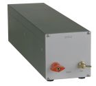
Special - LISN
- Details
Pilot ISN - Impedance Stabilisation Network
|
|
The Pilot ISN has an impedance of 150 Ω according to the standard as long as a PLC connection with an impedance of 100 Ω is established. The integrated attenuator improves the impedance matching and has to be switched on.
|
||||||||||||||||||||||||
- Details
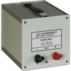
ECSS LISN 1
|
|
|
||||||||||||||||||||||||||||||
- Details
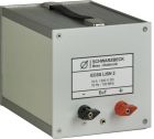
ECSS LISN 2
|
|
|
||||||||||||||||||||||||||||||
- Details
ECSS LISN 2 - 75A
|
|
The device under test may drain a continuous current of 75 A and for a short period of time it may even drain more than 100 A.
|
||||||||||||||||||||||||||||||
- Details
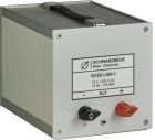
ECSS LISN 3
|
|
|
||||||||||||||||||||||||||||||
- Details
PVDC 8301 - DC-AMN (LISN)
|
|
The symmetric DC-LISN PVDC 8301 can be used for measuring the disturbance voltage in the frequency range from 0.15 MHz to 30 MHz on photovoltaic inverters. Up to now the conducted emissions of photovoltaic inverters at the mains terminals were usually measured using LISN according to CISPR 16-1- 2. The circuit concepts of PV-inverters may cause ripple currents on the DC-side of the inverter, though. These ripple currents, which mostly are in direct proportion to the mains frequency, are passing through the cabling and the PV-generator modules and can be radiated as magnetic fields with sometimes remarkable disturbance effect. Traditional measurements at the PV-inverters' AC terminals will not be able to reveal such disturbance phenomena. The PVDC 8301 was especially designed to measure all kinds of disturbance voltages at the DC-side of photovoltaic inverters. These are in detail the disturbance voltage of one conductor above reference ground (unsymmetrical disturbance voltage), the common mode disturbance volage of a pair of conductors above ground (asymmetrical disturbance voltage) and finally, the differential mode voltage between two conductors.
|
||||||||||||||||||||||||||||||||||||||||||
- Details
PVDC 8300 - DC-AMN (LISN)
|
|
The symmetric DC-LISN PVDC 8300 can be used for measuring the disturbance voltage in the frequency range from 0.15 MHz to 30 MHz on photovoltaic inverters. Up to now the conducted emissions of photovoltaic inverters at the mains terminals were usually measured using LISN according to CISPR 16-1- 2. The circuit concepts of PV-inverters may cause ripple currents on the DC-side of the inverter, though. These ripple currents, which mostly are in direct proportion to the mains frequency, are passing through the cabling and the PV-generator modules and can be radiated as magnetic fields with sometimes remarkable disturbance effect. Traditional measurements at the PV-inverters' AC terminals will not be able to reveal such disturbance phenomena. The PVDC 8300 was especially designed to measure all kinds of disturbance voltages at the DC-side of photovoltaic inverters. These are in detail the disturbance voltage of one conductor above reference ground (unsymmetrical disturbance voltage), the common mode disturbance volage of a pair of conductors above ground (asymmetrical disturbance voltage) and finally, the differential mode voltage between two conductors.
|
||||||||||||||||||||||||||||||||||||||||||
- Details
TEMP 8400 - Tempest LISN
|
|
The symmetrical AC-network TEMP 8400 consists of two identical channels for the lines "A" and "B". It is constructed with air core inductors, in order to avoid intermodulation interference. For the evaluation of interference phenomena the unsymmetrical interference voltage of a conductor to ground reference in the frequency range of 9 kHz to 1 GHz can be measured. Lower-frequency interference that may cause damage to the measuring receiver input shall be mitigated by additional high-pass filters.
Accessories: TEMP 8401 Adapter N-male to wing terminals for TEMP 8400
|
|||||||||||||||||||||||||||||||||
- Details
NPLC 8500 - Line Impedance Stabilization Network
|
|
To determine the power spectral density of PRIME transceivers (PoweRline Intelligent Metering Evolution) the unsymmetrical voltage between a conductor and ground has to be measured within the frequency range of 3 kHz to 148 kHz.
|
|||||||||||||||||||||||||||||||||


