
")

Dipoles
- Details
Tuned half-wave dipoles have been among the most important antennas from the
beginning of rf-technique. The characteristics of half-wave dipoles have
been calculable very early using the Maxwell and Hertz equations. Therefore the half
wave dipole became a reference antenna. The ideal (lossless) half-wave dipole has an
isotropic gain of 2.15 dBi and an impedance of 73 Ohm. The directional pattern is circular in
the H-plane, "8-shaped" in the E-plane with the maxima perpendicular on the dipole axis.
The half-power beamwidth (-3 dB) is approx. 78°. The impedance of real dipoles is
depending on the thickness/length ratio of its elements, typical values are 60-70 Ohm.
Dipoles for industrial applications are available in the frequency range from 30
MHz to up to approx. 4 GHz. The dipole elements are length variable (telescopic) or
with fixed length, the latter especially above 1 GHz. The most important applications are
test site evaluations (NSA, normalized site attenuation) and the determination of ERP
(Effective Radiated Power) respectively EIRP (Effective Isotropic Radiated Power).
|
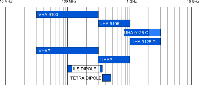
VHA 9103
VHF Half-Wave Dipole with 2 sets of telescopic elements 30-300 MHz
|
||
| |
UHA 9105
Tuneable UHF - Half - Wave Dipole 300 - 1000 MHz w. telescopic elements
|
|
| |
UHA 9125 C
Tuneable UHF - Half -Wave Dipole with EMI -Balun 0.75 - 2 GHz with 4 sets of elements LE = 180, 140, 100, 80 mm
|
|
| |
UHA 9125 D
Tuneable UHF - Half - Wave Dipole with EMI - Balun 1.0 - 3 (4) GHz with 6 sets of elements LE = 140, 114, 90, 72, 60, 48 mm
|
|
| |
VHAP
VHF Precision Dipole 30-300 MHz 2 sets of telescopic elements (mostly required in pairs) CISPR 16-1-5
|
|
|
VHAPA
Calibration adaptor for VHAP Precision Dipoles
|
||
|
CCA
Carrying and storing case for 2 x VHAP or 2 x UHAP cases for other antennas also available.
|
||
| |
UHAP
UHF Precision Dipole 300-1000 MHz (VHAP & UHAP mostly required in pairs) CISPR 16-1-5
|
|
|
UHAPA
Calibration adaptor for UHAP Precision Dipoles
|
||
| |
ILS Dipole
Linear polarized half-wave dipole with 1:1 balun and fixed element length for fieldstrength measurements at instrument landing systems (ILS).
Frequency range: localizer: 108 - 118 MHz (LOC, LLC) glideslope: 320 - 340 MHz (G/S) Gain: 1.5 dBi |
|
| |
TETRA DIPOLE
Linear polarized half-wave dipole with 1:1 balun and fixed element length for measurements at TETRA (terrestrical trunked radio) networks.
Frequency range: 340 - 480 MHz Gain: typ. 1.5 dBi
|
|


